日志
以太网开放系统介绍
| ||
OSI参考模型(Open System Interconnect Reference Model,开放系统互联参考模型) :A seven?layer abstract reference model for communications protocols in which each layer performs a specific task. The intent of the model is to allow different vendors on different hardware to communicate with each other at the same layer. The seven layers are physical, data link, network, transport, session, presentation, and application.
一种通信协议的7层抽象的参考模型,其中每一层执行某一特定任务。该模型的目的是使各种硬件在相同的层次上相互通信。这7层是:物理层、数据链路层、 网路层、传输层、话路层、表示层和应用层。
IEEE 802.3委员会的工作范畴是在OSI参考模型(Open System Interconnect Reference Model,开放系统互联参考模型)下面的物理层和数据链路层。
物理层定义了数据传送与接收所需要的电与光信号、线路状态、时钟基准、数据编码和电路等,并向数据链路层设备提供标准接口(RGMII / GMII / MII)。
数据链路层则提供寻址机构、数据帧的构建、数据差错检查、传送控制、向网络层提供标准的数据接口等功能。
这两层的每一层又分成若干子层和接口。下图显示了IEEE 802.3 Local and metropolitan area networks标准Part 3: Carrier sense multiple access with collision detection (CSMA/CD) access method and physical layer specifications规定的以太网的子层和接口。

IEEE 802.3标准把物理层从低到高分成如下子层和接口。
MDI(Medium Dependent Interface,媒体相关接口):规范物理媒体信号和传输媒质与物理设备之间的机械和电气接口。
PMD(Physical Medium Dependent,物理媒体相关)子层:位于MDI之上的PMD负责与传输媒体的接口。
PMA(Physical Medium Attachment,物理媒体附加)子层:负责发送、接收、定时恢复和相位对准功能。
PCS(Physical Coding Sublayer,物理编码子层):负责把数据比特编成合适物理媒质传输的码组。
GMII(Gigabit Media Independent Interface,吉比特媒质无关接口):吉比特MAC和吉比特物理层之间的GMII允许多个数据终端设备混合使用各种吉比特速率物理层。
RS(Reconciliation Sublayer,协调子层):提供GMII信号到MAC层的映射。
数据链路层由下列子层组成(由下到上顺序):
MAC(Media Access Control,媒体访问控制)子层:负责向物理层的数据转发功能(与媒介无关)。一般地来说,MAC子层负责封装(成帧、地址标示、差错检测)和媒体接入(冲突监测和延时过程)功能。
MAC Control(MAC控制)子层:MAC Control是可选的子层,负责MAC子层操作的实时控制和处理。定义了MAC控制子层以允许未来加入新功能。
LLC(Logical Link Control,逻辑链路控制)子层:负责数据链路层与媒体访问无关的功能,它不在IEE 802.3标准的范畴之内。MAC层和可选的MAC控制子层并不知晓上面是否存在LLC子层或者是其他客户(如网桥或中继器)。
The Ethernet MAC and PHY implement the bottom two layers of the International Organization for Standardization/Open System Interconnect (ISO/OSI) stack. The MAC interfaces with the PHY through an MII. The typical 10/100 PHY Ethernet implementation incorporates separate 10BaseT and 100BaseTX interfaces.
以太网PHY和MAC实现国际标准化组织(ISO,International Organization for Standardization)开放系统互连(OSI,Open System Interconnect)(ISO/OSI) 协议栈的下两层。MAC通过MII和PHY接口。典型的10兆和100兆PHY以太网实现分别和10BaseT和100BaseTX接口结合。

The PHY is the physical interface transceiver. It implements the physical layer. The IEEE-802.3 standard defines the Ethernet PHY. It complies with the IEEE-802.3 specifications for 10BaseT (clause 14) and 100BaseTX (clauses 24 and 25).
PHY是物理接口收发器,它实现物理层。IEEE-802.3标准定义了以太网PHY。它符合IEEE-802.3k中用于10BaseT(第14条)和100BaseTX(第24条和第25条)的规范。
The MAC is the media access controller. The Ethernet MAC is defined by the IEEE-802.3 Ethernet standard. It implements a data-link layer. The latest MACs support operation at both 10 Mbits/s and 100 Mbits/s. This crop typically implements the MII.
MAC是媒体访问控制器。以太网MAC由IEEE-802.3以太网标准定义。它实现了数据链路层。最新的MAC同时支持10/100/1000Mbps速率。通常情况下,它实现MII/GMII/RGMII接口,来同行业标准PHY器件实现接口。
IEEE 802.3标准还规范了以下兼容性接口(Compatibility interfaces)
The following important compatibility interfaces are defined within what is architecturally the Physical Layer. 下列重要的兼容性接口被定义在物理层架构里。
a) Medium Dependent Interfaces (MDI). To communicate in a compatible manner, all stations shall adhere rigidly to the exact specification of physical media signals defined in Clause 8 (and beyond) in this standard, and to the procedures that define correct behavior. of a station. The medium-independent aspects of the LLC sublayer and the MAC sublayer should not be taken as detracting from this point; communication by way of the ISO/IEC 8802-3 [IEEE Std 802.3] Local Area Network requires complete compatibility at the Physical Medium interface (that is, the physical cable interface).
a)媒体相关接口。为了以兼容的方式通讯,所有站点会严格遵照在本标准字句8(及以后)定义的物理层媒体信号的确切规格,并且严格遵照定义站点正确行为的规程。LLC子层和MAC子层的媒体无关方面不应该被认为从这一点减损;通过ISO/IEC 8802-3 [IEEE Std 802.3]局域网方式通讯需要在物理媒体接口上完全兼容(即,物理电缆接口)。
b) Attachment Unit Interface (AUI). It is anticipated that most DTEs will be located some distance from their connection to the physical cable. A small amount of circuitry will exist in the Medium Attachment Unit (MAU) directly adjacent to the physical cable, while the majority of the hardware and all of the software will be placed within the DTE. The AUI is defined as a second compatibility interface. While conformance with this interface is not strictly necessary to ensure communication, it is recommended, since it allows maximum flexibility in intermixing MAUs and DTEs. The AUI may be optional or not specified for some implementations of this standard that are expected to be connected directly to the medium and so do not use a separate MAU or its interconnecting AUI cable. The PLS and PMA are then part of a single unit, and no explicit AUI implementation is required.
连接单元接口(AUI)。也称为附件单元接口。预计大部分的DTE(Data Terminal Equipment,数据终端设备)将被置于离他们到物理电缆连接一段距离。少量的电路将存在于直接毗邻物理电缆的媒体连接单元(MAU,Medium Attachment Unit ),而大部分的硬件和所有的软件都将被放置在DTE中。AUI被定义为第二兼容性接口。虽然为确保通信,和这种接口的一致性不严格必须,但是和这种接口的兼容性是建议的,因为它允许在混杂MAU和DTE的最大的灵活性。AUI可能是可选的或不为本标准的一些实现指定,这些实现预计将直接连接到媒体,所以不使用单独的MAU或它的互联AUI电缆。然后,PLS(Physical Layer Signaling,物理层信令)和PMA(Physical Medium Attachment,物理媒体附加)是单个单位的一部分,显式的AUI实现是不必要的。
AUI 端口是用来与粗同轴电缆连接的接口,它是一种"D"型15针接口,这在令牌环网或总线型网络中是一种比较常见的端口之一。路由器可通过粗同轴电缆收发器实现与10Base-5网络的连接,但更多的是借助于外接的收发转发器(AUI-to-RJ-45),实现与10Base-T以太网络的连接。当然也可借助于其他类型的收发转发器实现与细同轴电缆(10Base-2)或光缆(10Base-F)的连接。这里所讲的路由器AUI接口主要是用粗同轴电缆作为传输介质的网络进行连接用的,AUI接口示意图如图所示。
AUI:Attachment Unit Interface 连接单元接口
c) Media Independent Interface (MII). It is anticipated that some DTEs will be connected to a remote PHY, and/or to different medium dependent PHYs. The MII is defined as a third compatibility interface. While conformance with implementation of this interface is not strictly necessary to ensure communication, it is recommended, since it allows maximum flexibility in intermixing PHYs and DTEs. The MII is optional.
媒体独立接口(MII,Meida Independent Interface)。预计一些DTE将被连接到远程的PHY上,并且/或者连接到不同的媒体相关的PHYs。MII被定义为第三兼容接口。 而为确保通信,与此接口实现相一致性不严格必须,和这种接口的兼容性是建议的,因为它允许在混杂PHY和DTE的最大的灵活性。MII是可选的。
The Media Independent Interface (MII) is an Ethernet industry standard defined in IEEE 802.3. It consists of a data interface and a management interface between a MAC and a PHY (Fig. 1). The data interface consists of a channel for the transmitter and a separate channel for the receiver. Each channel has its own clock, data, and control signals. The MII data interface requires a total of 16 signals. The management interface is a two-signal interface—one signal for clocking and the other for data. With the management interinterface, upper layers can monitor and control the PHY.
媒体独立接口(MII,Medium Independent Interface)是IEEE-802.3定义的以太网行业标准。它包括一个数据接口,以及一个MAC和PHY之间的管理接口。
数据接口包括分别用于发送器和接收器的两条独立信道。每条信道都有自己的数据、时钟和控制信号。MII数据接口总共需要16个信号。
管理接口是个双信号接口:一个是时钟信号,另一个是数据信号。通过管理接口,上层能监视和控制PHY。
MII标准接口用于连快Fast Ethernet MAC-block与PHY。“介质无关”表明在不对MAC硬件重新设计或替换的情况下,任何类型的PHY设备都可以正常工作。在其他速率下工作的与 MII等效的接口有:AUI(10M 以太网)、GMII(Gigabit 以太网)和XAUI(10-Gigabit 以太网)。
此外还有RMII(Reduced MII)、GMII(Gigabit MII)、RGMII(Reduced GMII)SMII等。所有的这些接口都从MII而来,MII是(Medium Independent Interface)的意思,是指不用考虑媒体是铜轴、光纤、电缆等,因为这些媒体处理的相关工作都有PHY或者叫做Framer的芯片完成。
MII支持10兆和100兆的操作,一个接口由14根线组成,它的支持还是比较灵活的,但是有一个缺点是因为它一个端口用的信号线太多,如果一个8端口的交换机要用到112根线,16端口就要用到224根线,到32端口的话就要用到448根线,一般按照这个接口做交换机,是不太现实的,所以现代的交换机的制作都会用到其它的一些从MII简化出来的标准,比如RMII、SMII、GMII等。
RMII是简化的MII接口,在数据的收发上它比MII接口少了一倍的信号线,所以它一般要求是50兆的总线时钟。RMII一般用在多端口的交换机,它不是每个端口安排收、发两个时钟,而是所有的数据端口公用一个时钟用于所有端口的收发,这里就节省了不少的端口数目。RMII的一个端口要求7个数据线,比MII少了一倍,所以交换机能够接入多一倍数据的端口。和MII一样,RMII支持10兆和100兆的总线接口速度。
SMII是由思科提出的一种媒体接口,它有比RMII更少的信号线数目,S表示串行的意思。因为它只用一根信号线传送发送数据,一根信号线传输接受数据,所以在时钟上为了满足100的需求,它的时钟频率很高,达到了125兆,为什么用125兆,是因为数据线里面会传送一些控制信息。SMII一个端口仅用4根信号线完成100兆信号的传输,比起RMII差不多又少了一倍的信号线。SMII在工业界的支持力度是很高的。同理,所有端口的数据收发都公用同一个外部的125M时钟。
GMII是千兆网的MII接口,这个也有相应的RGMII接口,表示简化了的GMII接口。
MII总线:在IEEE802.3中规定的MII总线是一种用于将不同类型的PHY与相同网络控制器(MAC)相连接的通用总线。网络控制器可以用同样的硬件接口与任何PHY连接。
简化媒体独立接口(RMII,Reduced Media Independant Interface) 是标准的以太网接口之一,比MII有更少的I/O传输。
RMII和MII对比:RMII是用两根线来传输数据的, MII是用4根线来传输数据的, GMII是用8根线来传输数据的。
MII/RMII只是一种接口,对于10M线速,MII的速率是2.5M,RMII则是5M;对于100M线速,MII的速率是25M,RMII则是50M。
MII/RMII用于传输以太网包,在MII/RMII接口是4/2bit的,在以太网的PHY里需要做串并转换、编解码等才能在双绞线和光纤上进行传 输,其帧格式遵循IEEE 802.3(10M)/IEEE 802.3u(100M)/IEEE 802.1q(VLAN)。
以太网帧的格式为:前导符(7Bytes)+开始位(1Bytes)+目的mac地址+源mac地址+类型/长度+数据+padding(optional)+FSC(32bitCRC )如果有vlan,则要在类型/长度后面加上2个字节的vlan tag,其中12bit来表示vlan id,另外4bit表示数据的优先级!
d)Gigabit Media Independent Interface (GMII).
The GMII is designed to connect a 1 Gb/s capable gigabit-capable MAC or repeater unit to a 1 Gb/s gigabit PHY. While conformance with implementation of this interface is not strictly necessary to ensure communication, it is highly recommended, since it allows maximum flexibility in intermixing PHYs and DTEs at 1 Gb/s gigabit speeds. The GMII is intended for use as a chip-to-chip interface. No mechanical connector is specified for use with the GMII. The GMII is optional.
吉比特媒体独立接口(GMII,Gigabit Media Independent Interface)GMII设计用来连接1Gbps能力的千兆MAC或中继器单元到1Gbps千兆PHY。而为了确保通信,与此接口实现的一致性不是严格必须的,我们强烈建议,因为在以1千兆的速率混杂PHY和DTE时,它允许最大的灵活性。GMII设计用作芯片到芯片接口。无机械连接器被指定为和GMII一起使用。是的GMII是可选的。
GMII (Gigabit MII)GMII采用8位接口数据,工作时钟125MHz,因此传输速率可达1000Mbps。同时兼容MII所规定的10/100 Mbps工作方式。
GMII接口数据结构符合IEEE以太网标准。该接口定义见IEEE 802.3-2000。
发送器:
◇ GTXCLK——吉比特TX..信号的时钟信号(125MHz)
◇ TXCLK——10/100M信号时钟
◇ TXD[7..0]——被发送数据
◇ TXEN——发送器使能信号
◇ TXER——发送器错误(用于破坏一个数据包)
注:在千兆速率下,向PHY提供GTXCLK信号,TXD、TXEN、TXER信号与此时钟信号同步。否则,在10/100M速率下,PHY提供TXCLK时钟信号,其它信号与此信号同步。其工作频率为25MHz(100M网络)或2.5MHz(10M网络)。
接收器:
◇ RXCLK——接收时钟信号(从收到的数据中提取,因此与GTXCLK无关联)
◇ RXD[7..0]——接收数据
◇ RXDV——接收数据有效指示
◇ RXER——接收数据出错指示
◇ COL——冲突检测(仅用于半双工状态)
管理配置
◇ MDC——配置接口时钟
◇ MDIO——配置接口I/O
管理配置接口控制PHY的特性。该接口有32个寄存器地址,每个地址16位。其中前16个已经在“IEEE 802.3,2000-22.2.4 Management Functions”中规定了用途,其余的则由各器件自己指定。
e) Ten-bit Interface (TBI). The TBI is provided by the 1000BASE-X PMA sublayer as a physical
instantiation of the PMA service interface. The TBI is recommended for 1000BASE-X systems,
since it provides a convenient partition between the high-frequency circuitry associated with the
PMA sublayer and the logic functions associated with the PCS and MAC sublayers. The TBI is
intended for use as a chip-to-chip interface. No mechanical connector is specified for use with the
TBI. The TBI is optional.
10比特接口(TBI,Ten-bit Interface )。TBI被1000BASE-X的PMA(Physical Medium Attachment,物理媒体附加)子层提供作为PMA服务接口的物理实例化。TBI被推荐给1000BASE-X系统,因为它提供了PMA子层相关高频电路与PCS、MAC子层相关逻辑功能之间的便利区分。TBI设计用作芯片到芯片的接口。无机械连接器被指定为何TBI一起使用。TBI是可选的。
f) 10 Gigabit Media Independent Interface (XGMII). The XGMII is designed to connect a 10 Gb/s
capable MAC to a 10 Gb/s PHY. While conformance with implementation of this interface is not
strictly necessary to ensure communication, it is recommended, since it allows maximum flexibility
in intermixing PHYs and DTEs at 10 Gb/s speeds. The XGMII is intended for use as a chip-to-chip
interface. No mechanical connector is specified for use with the XGMII. The XGMII is optional.
10吉比特媒体独立接口(XGMII,10 Gigabit Media Independent Interface )。XGMII被设计用于连接10Gbps能力的MAC到10Gbps的PHY。而为了确保通信,与此接口实现相一致性不严格必须,和这种接口的兼容性是建议的,因为它允许以10Gbps速率混杂PHYs和DTEs时最大的灵活性。XGMII设计用作芯片到芯片的接口。无机械连接器被指定为和XGMII一起使用。XGMII是可选的。
g) 10 Gigabit Attachment Unit Interface (XAUI). The XAUI is designed to extend the connection
between a 10 Gb/s capable MAC and a 10 Gb/s PHY. While conformance with implementation of
this interface is not strictly necessary to ensure communication, it is recommended, since it allows
maximum flexibility in intermixing PHYs and DTEs at 10 Gb/s speeds. The XAUI is intended for
use as a chip-to-chip interface. No mechanical connector is specified for use with the XAUI. The
XAUI is optional.
10吉比特连接单元接口(XAUI,10 Gigabit Attachment Unit Interface)。XAUI 被设计用于扩展10 Gbps能力得到MAC和10 Gbps的PHY之间的连接。而为确保通信,与此接口实现相一致性不严格必须,和这种接口的兼容性是建议的,因为它允许以10Gbps速率混杂PHYs和DTEs时最大的灵活性。XAUI设计用作芯片到芯片的接口。无机械连接器被指定为和XAUI一起使用。XAUI是可选的。
Under the International Standards Organization’s Open Systems Interconnection (OSI) model, Ethernet is fundamentally a Layer 2 protocol. An Ethernet PHYsical layer device (PHY), which corresponds to Layer 1 of the OSI model, connects the media (optical or copper) to the MAC layer, which corresponds to OSI Layer 2.
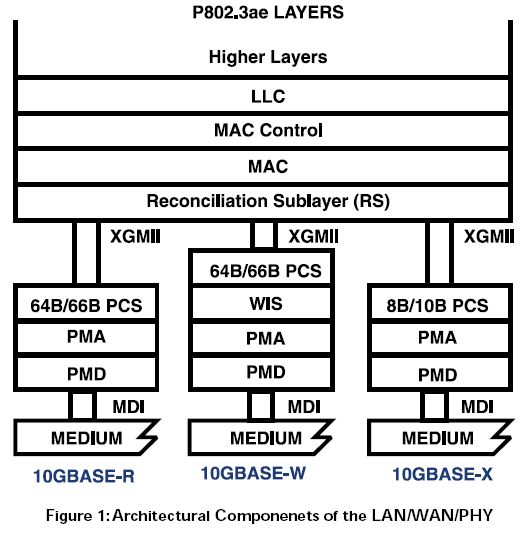
The 802.3ae specification defines two PHY types: the LAN PHY and the WAN PHY. The WAN PHY has an extended feature set added onto the functions of a LAN PHY. Ethernet architecture further divides the PHY (Layer 1) into a Physical Media Dependent (PMD) and a Physical Coding Sublayer (PCS). The two types of PHYs are solely distinguished by the PCS.
802.3ae规范定义了两种PHY类型:LAN PHY和WAN PHY。WAN PHY有一个附加到LAN PHY功能上的扩展特性集。以太网架构进一步划分PHY(1层)为PMD(Physical Media Dependent,物理媒体相关)和PCS(Physical Coding Sublayer,物理编码子层)。这两种类型的PHYs被PCS各自区分开。
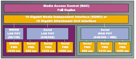
IEEE 802.3ae PHY系列
10GbE标准框架包含两个新的物理层规范:LAN PHY和WAN PHY。另外还有三种PCS子层:10GBASE-X、10GBASE-R和10GBASE-W。前两个属于LAN PHY系列,最后一个属于WAN PHY。
LAN PHY和WAN PHY的区别在于帧类型和接口速度。串行LAN PHY(10GBASE-R)采用的是以太网帧,数据速率为10.3125Gb/s(MAC的运行速度为10.000Gb/s;加上64B/66B的编码开销,实际的线路速率为10.000* 66/64=10.3125Gb/s)。而WAN PHY则可以将64B/66B编码负荷包装到一个通过SONET连接的STS-192c帧中,数据速率为9.953Gb/s。
我们为什么需要WAN PHY?
SONET/SDH是光传输网络上采用的主要技术,因而传统的光传输基础设施都建立在工作速率为9.953Gb/s的SONET/SDH协议的基础上。但是,线路速率为10.3125Gb/s的LAN PHY与SONET/SDH的速率不匹配,因而不能在基于SONET/SDH的WAN上传输。WAN PHY是IEEE为让10GbE数据速率适应SONET/SDH速度而提供的方法。
WAN PHY可以让10GbE兼容ANSI定义的SONET STS-192c格式和数据速率,以及ITU规定的SDH VC-4-64c容器。WAN PHY并不是严格兼容SONET。它更适于被形容为10GbE的一种适应SONET的变体。它的光传输规格和延时、抖动要求仍然与SONET/SDH网络截然不同。
Figure 1 gives a graphical overview of the architectural components of the LAN / WAN PHY
Between the MAC and the PHY is the XGMII, or 10 Gigabit Media Independent Interface. The XGMII provides full duplex operation at a rate of 10 Gb/s between the MAC and PHY. Each direction is independent and contAIns a 32-bit data path, as well as clock and control signals. In total the interface is 74 bits wide.
While XGMII provides a 10 Gb/s pipeline, the separate transmission of clock and data coupled with the timing requirement to latch data on both the rising and falling edges of the clock results in significant challenge in routing the bus more than the recommended short distance of 7 cm. For this reason, chip-to-chip, board-to-board and chip-to-optical module applications are not practical with this interface. Consequently, the XGMII bus puts many limitations on the number of ports that may be implemented on a system line card.
To overcome these issues, the 10 Gigabit Ethernet Task Force developed the XAUI interface. XAUI is a full duplex interface that uses four (4) self-clocked serial differential links in each direction to achieve 10 Gb/s data throughput. Each serial link operates at 3.125 Gb/s to accommodate both data and the overhead associated with 8B/10B coding. The self-clocked nature eliminates skew concerns between clock and data, and extends the functional reach of the XGMII by approximately another 50 cm. Conversion between the XGMII and XAUI interfaces occurs at the XGXS (XAUI Extender Sublayer).
XGMII和XAUI:在MAC和物理层之间是XGMII,XGMII为10吉比特全双工接口,其宽度为74bit,其中数据通道为64bit(单向数据通道为32bit),其余的为时钟和控制信号比特,它是连接以太网MAC层和物理层的桥梁。当XGMII提供10吉比特的数据通道时,由于时钟比特和数据比特再加上在时钟上升沿和下降沿锁存数据的定时要求,会导致路由选择的总线长度超出通常建议的7cm,因此使用XGMII总线会对系统线卡的端口数量产生很大限制,所以在芯片之间、各种板之间,以及芯片和光学组件之间的接口一般不选用此接口。
为了克服这些困难,人们就提出了10吉比特连接单元接口(10Gigabit Attachment Unit Interface, XAUI)。XAUI是10吉比特以太网的重大变化之一,它能极大地改进和简化互连的路由选择。XAUI接口是一个全双工接口,它分别在两个方向上使用4对自同步串行链路来实现10Gbit/s的吞吐量。每一个串行链路使用8B/10B编码传送数据和开销,其工作速率为3.125Gbit/s,自同步特性消除了时钟和数据的相位偏移。XGMII和XAUI接口之间的转换由XAUI扩展子层(XAUI Extender Sublayer, XGXS)完成,在XAUI接口的信号源侧,某给定线上的数据和时钟字节在XGXS中被转变成8B/10B编码数据流。每对线上的数据流传输速率为3.125Gbit/s。在互连的信号宿侧,将时钟信号从到达的数据流中提取出来,再通过解码,重新映射成32bit XGMII格式。这样,74针的XGMII接口可以减少成8对即16针的XAUI接口;而且,XAUI的信源同步时钟方案允许XAUI交叉时钟域,从而在系统中除去复杂的定时校正。由于XAUI接口结构紧凑,性能健壮,因此很适合用于芯片之间、各种板之间,以及芯片和光学组件之间。
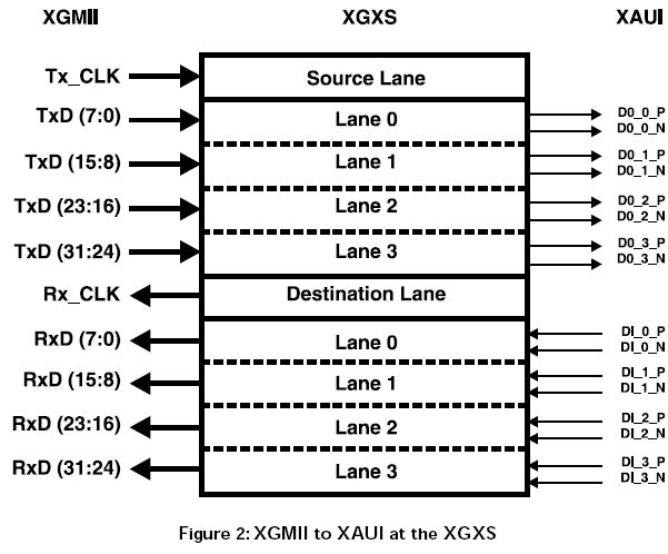
As seen in Figure 2, the XGMII interface is organized into 4 lanes of 8 bits. At the source side of the XAUI interface bytes on a given lane as well as the timing clock are converted within the XGXS into an 8B / 10B encoded data stream. Each data stream is transmitted across a single differential pair running at 3.125 Gb/s. At the destination side of the interconnect the clock is recovered from the incoming data stream, it is decoded and then mapped back to the 32 bit XGMII format. . Thus, the 74 pin wide XGMII interface is reduced to a XAUI interface consisting of 8 differential pair or 16 pins. Furthermore, the source synchronous clocking scheme allows XAUI to cross clock domains, which eliminates elaborate timing correction within the system.
XAUI – A Self-Managed Interface
The XAUI employs the same robust 8B/10B transmission code as 1000BASE-X. With 8b/10b coding, there are more than enough code possibilities for mapping an 8-bit word. Some of the extra code groups are used for control signaling; such as start of frame, end of frame, channel idle, link configurations and so on. Control words are used during the Inter-Packet Gap (IPG) time and during idle periods to continuously allow the interface to maintain word and lane allignment. This is done with no upper layer support requirement, and allows XAUI to function as a self-managed interface.
Frame. synchronization and lane alignment is essentially a two-step process. Code group synchronization is achieved on each lane upon reception of three ordered sets for the lane. One easily recognizable patterns called comma /K/ enables the XAUI receiver to attain frame. alignment on the incoming bit stream. Each lane adjusts for proper alignment to the /K/ whenever it appears. However, each serial transmission lane operates independently and can often come out of alignment with respect to one another. As shown in Figure 3, lane alignment is accomplished by use of a control word defined for alignment, referred to as /A/. The XAUI line protocol defines specific times during the IPG when an /A/ word should be passed on all four lanes simultaneously. The receiving connection uses these words to correct for lane-to-lane skew common in most connections. The XAUI interface can lane align with up to 40bits (12.8ns) of skew between lanes, allowing for significant flexibility in board design.
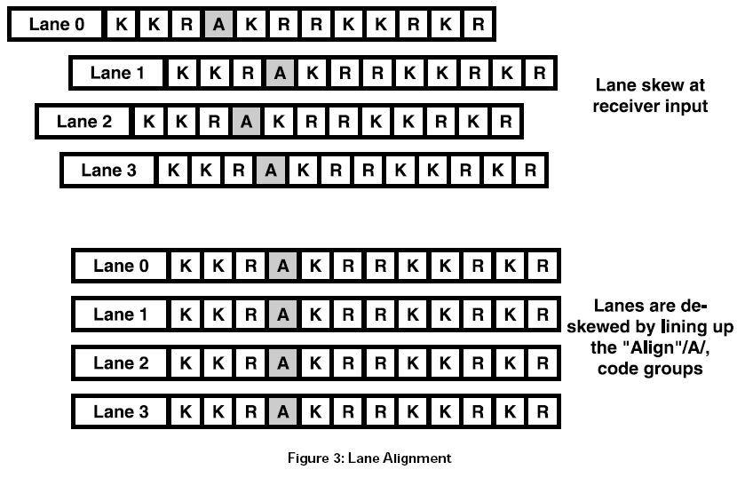
Furthermore, XAUI compensates for differences in clock domains that often exist between each side of the link. By monitoring the difference between incoming and outgoing data rates, each XAUI connection can add or delete specific control words in the IPG, referred to as /R/ to balance the data rate at each connection without effecting lane disparity.
XAUI interoperability
The 10 Gigabit Ethernet Alliance formed a working group to examine interoperability between different vendors’ XAUI implementation. This group worked in conjunction with the 10 Gigabit Ethernet Consortium to define the test methodology and environment under which interoperability testing would be performed. The 10 Gigabit Ethernet Consortium, which will be responsible for performing interoperability testing between different vendors’ XAUI implementation, has adopted the work completed by this group.
Multiple vendors have demonstrated XAUI interoperability. All devices tested were designed to the IEEE 802.3ae pecification. Each vendor has demonstrated bit error rates of 10-12 over PC board traces of 50 cm length, demonstrating the
robustness of the technology and completeness of the standard. The basic nature of XAUI enables it to be scaleable, which will provide users with a future upgrade path to extend the life of their systems. For more information on XAUI Interoperability testing, please visit the 10 Gigabit Ethernet Consortium at http://www.iol.unh.edu/consortiums/10gec.
The 10 Gigabit Attachment Unit Interface, “XAUI”, is a technical innovation that dramatically improves and simplifies the routing of electrical interconnections. It helps to overcome the length limitation associated with the XGMII, which provides full duplex operation at a rate of 10 Gb/s between the Ethernet MAC and PHY layers. By extending the physical separation between the MAC and PHY, the interface allows for fan-out on multi-port line cards or connections to other cards within the system chassis. In addition, the self-managed interface helps to overcome associated clocking issues, which leads to a more easily implemented solution.
h) 10 Gigabit Sixteen-Bit Interface (XSBI). The XSBI is provided as a physical instantiation of the
PMA service interface for 10GBASE-R and 10GBASE-W PHYs. While conformance with
implementation of this interface is not strictly necessary to ensure communication, it is recommended,
since it provides a convenient partition between the high-frequency circuitry associated
with the PMA sublayer and the logic functions associated with the PCS and MAC sublayers. The
XSBI is intended for use as a chip-to-chip interface. No mechanical connector is specified for use
with the XSBI. The XSBI is optional.
10吉比特16比特接口(XSBI,10 Gigabit Sixteen-Bit Interface )。XSBI被提供作为10GBASE-R和10GBASE-W PHYs的PMA(Physical Medium Attachment,物理媒体附加)服务接口的一个物理实例化。而为了确保通信,与此接口实现的一致性不严格必须,与此接口实现的一致性被建议,因为它提供了PMA子层相关高频电路与PCS、MAC子层相关逻辑功能之间的便利区分。XSBI设计用作芯片到芯片的接口。无机械连接器被指定为何XSBI一起使用。XSBI是可选的。

答:
吉比特以太网物理层协议及接口
吉比特以太网协议的数据链路层与传统的10/100Mb/s以太网协议相同,但物理层有所不同。三种协议与OSI七层模型的对应关系如图所示。

 /1
/1 
 eetop公众号
 创芯大讲堂
创芯大讲堂 创芯人才网
创芯人才网